
Network Profiles
A Network Profile specifies how a Machine attaches to your fabric:
- Which physical interfaces should form logical Uplinks
- Which Networks & Subnets are connected to those Uplinks ("Host Networks")
Uplinks
An Uplink groups the physical interfaces that attach a Machine to the fabric. Uplinks fall into the following categories:

Simplest setup: The Machine has exactly one interface that is connected to the switch. In this case, you can create an Uplink with mode "Auto-Detect", so you don't have to name the interface (which can change across hardware, OS versions etc.)
Example:
| Profile | Uplink | Mode | Interfaces |
|---|---|---|---|
prd | workload | Auto-detect | - |
Identifying interfaces
Interfaces are identified either by kernel name (eth0) or by MAC address.
We recommend using kernel names: the same Network Profile then fits every Machine that is cabled the same way, so a homogeneous fleet needs a single profile.
Sometimes you might not know the kernel names or prefer using MAC addresses; in that case you'll need to create one Network Profile per Machine, since the MAC address will only fit that particular Machine.
TIP
If you don't know the interface names or MAC addresses of your servers, create a Network Profile in mode Auto-detect and boot a server with an Enrollment Image using it. On a server with more than one interface, enrollment fails and the interfaces are printed on the serial console and in the Enrollment Logs:
this machine has:
  eno1  00:1b:21:3c:4d:5e  link up  25000Mb/s
      pci-0000:19:00.0 ixgbe
  eno2  00:1b:21:3c:4d:5f  no link
      pci-0000:19:00.1 ixgbe
Host Networks
A Host Network attaches an Uplink to one Subnet: the Machine gets an address on that segment via that Uplink.
You can further configure if the network uses VLAN tagging or not, so you end up with one of the following configurations:
Untagged
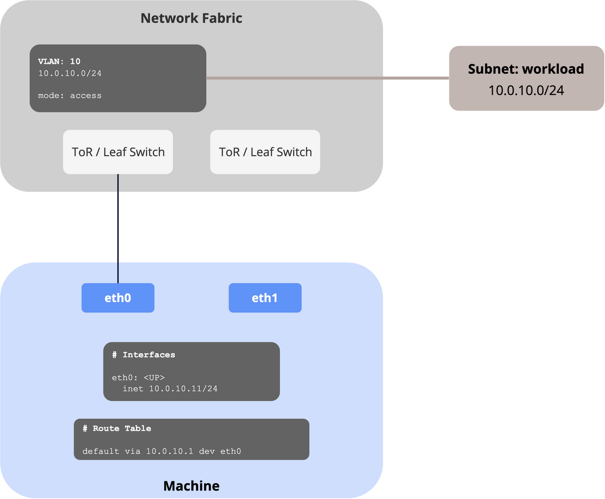
If the port is an access port (i.e. the frames travel without a VLAN tag - untagged - on the wire), disable "Tagged". The Machine gets its address directly on the Uplink device (eth0).
Example:
| Profile | Uplink | Mode | Interfaces | Subnet | Tagged |
|---|---|---|---|---|---|
prd | workload | Single | eth0 | workload | no |
As Terraform: single-homed, untagged.
Tagged
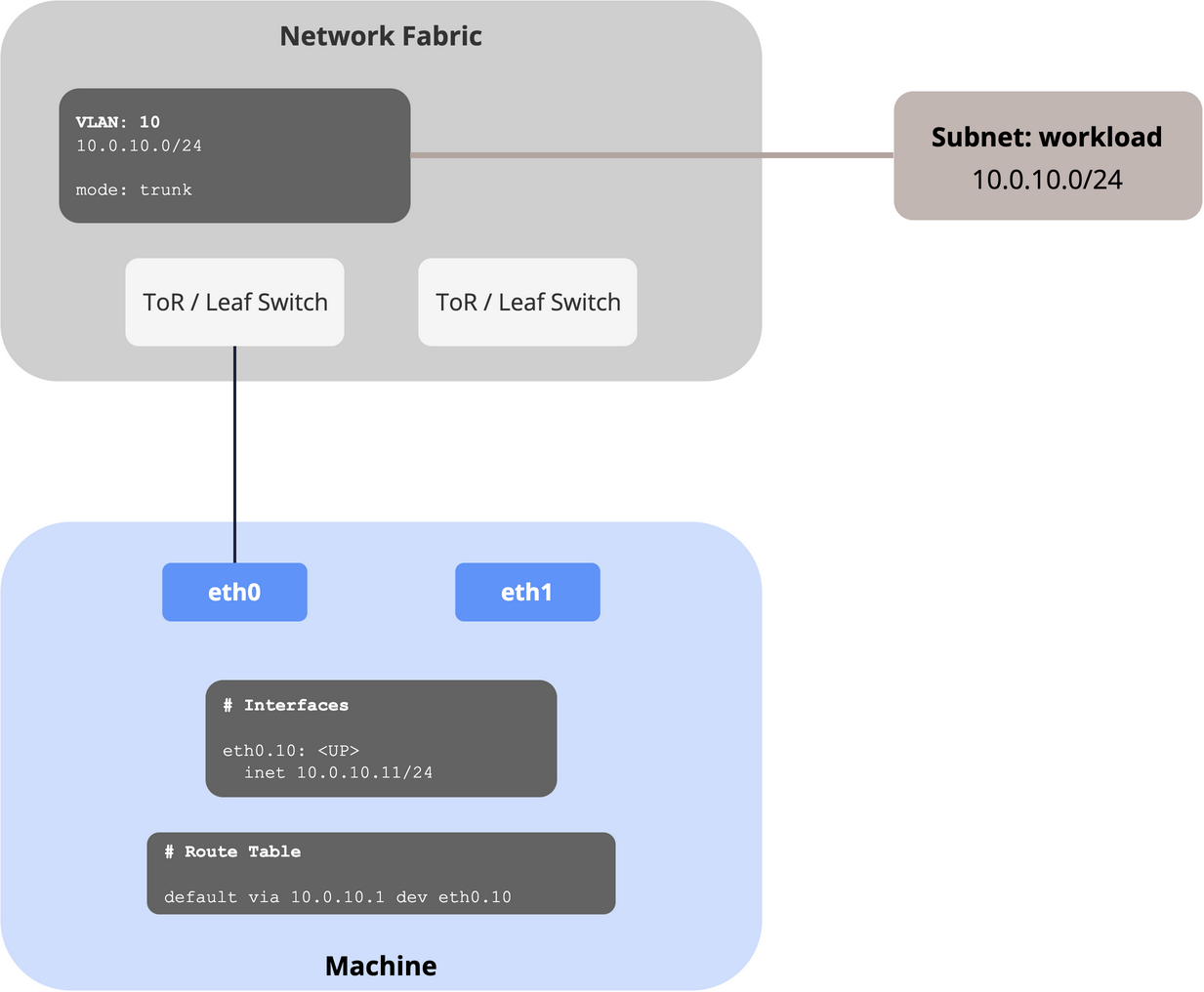
If the port is a trunk (i.e. the frames travel with a VLAN tag on the wire), enable "Tagged". The Machine then configures a subinterface (eth0.10) which gets the address.
Example:
| Profile | Uplink | Mode | Interfaces | Subnet | Tagged |
|---|---|---|---|---|---|
prd | workload | Single | eth0 | workload | yes |
As Terraform: single-homed, tagged.
Multiple Host Networks
You can also connect one Uplink to multiple Subnets.
Primary
If you use more than one Subnet, you must specify which Host Network is the Primary: the one that supplies the default route, the DNS resolver and NTP.
More specifically:
| Delivered by the primary Host Network only | Delivered by every Host Network |
|---|---|
| Gateway, DNS, NTP, Search Domains | Address, MTU, Routes |
WARNING
The primary Host Network is also the interface the kubelet advertises, so it has to be the one that reaches your control plane.
Let's look at the possible scenarios when you have multiple Host Networks:
All Subnets tagged
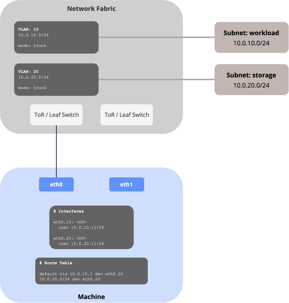
In this case, a single interface is connected to two tagged Subnets. Each one gets its own subinterface (eth0.10, eth0.20).
Example:
| Profile | Uplink | Mode | Interfaces | Subnet | Tagged | Primary |
|---|---|---|---|---|---|---|
prd | main | Single | eth0 | workload | yes | yes |
storage | yes | no |
As Terraform: multiple tagged Subnets.
One native Subnet
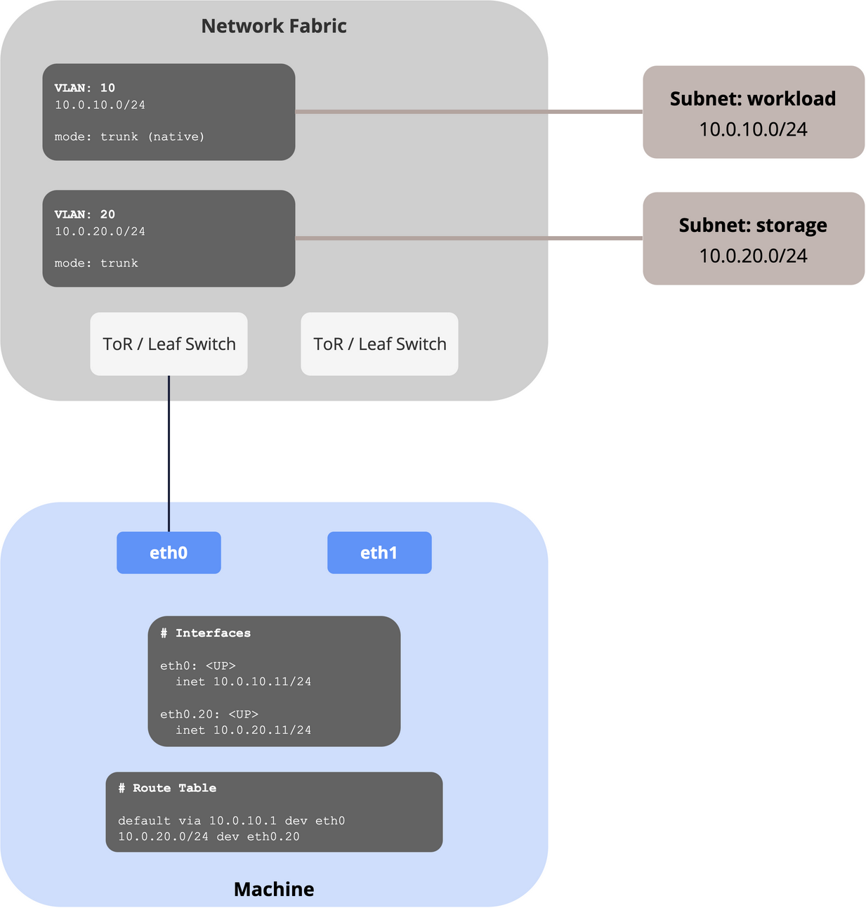
It's also possible to have one "native" VLAN (i.e. the untagged one, workload in that example) and additional tagged ones.
Example:
| Profile | Uplink | Mode | Interfaces | Subnet | Tagged | Primary |
|---|---|---|---|---|---|---|
prd | main | Single | eth0 | workload | no | yes |
storage | yes | no |
As Terraform: one native and one tagged Subnet.
Multiple Uplinks
You can optionally configure multiple Uplinks: create one Uplink for each group of interfaces that needs a configuration of its own.
A common use case is if you want to use different physical interfaces (and maybe even a different fabric) for separate purposes, for example for a dedicated workload and a dedicated storage network.
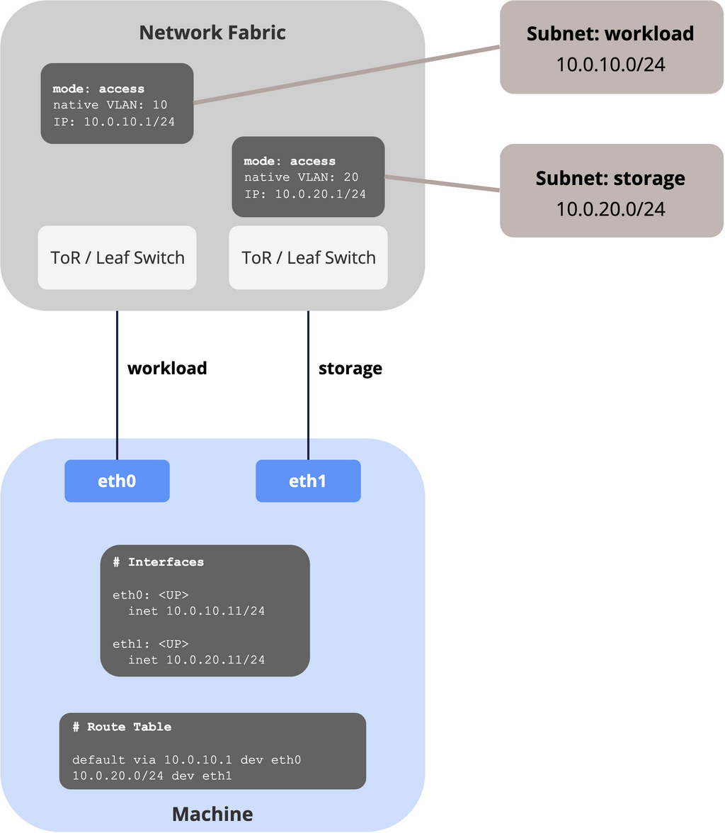
This example configures eth0 for the workload network and eth1 for the storage network. It uses untagged VLANs, but tagged VLANs would also be supported.
Example:
| Profile | Uplink | Mode | Interfaces | Subnet | Tagged | Primary |
|---|---|---|---|---|---|---|
prd | workload | Single | eth0 | workload | no | yes |
prd | storage | Single | eth1 | storage | no | no |
As Terraform: multiple Uplinks.
This list of scenarios is not exhaustive; you can further mix and match the different configurations, for example having multiple Subnets on multiple Uplinks.
Usage
Once Network Profiles are in place, they can be used in two places:
- Machine: A Machine uses a Network Profile as either Operational or Depot Network Profile (or both):
| Profile | Active when |
|---|---|
| Operational Network Profile | when assigned to a Machine Pool / Cluster and running Kubernetes workloads |
| Depot Network Profile | unassigned or in recovery |
- Enrollment Images: Newly enrolling Machines use Network Profiles to configure networking when registering themselves in meltcloud. If a Machine self-registers, it takes over the Network Profile from the Enrollment Image.
Depot Network
We recommend introducing a separate network that reaches meltcloud and nothing else: the depot network.
This can be used as neutral segment when Machines are not assigned to Clusters. Examples:
- Enrollment should happen in a neutral segment without connectivity to production systems.
- Machines are onboarded by one team (i.e. the infra team), put into the depot network, and then assigned to Clusters by another (or much later).
- Spare Machines wait in the rack, enrolled and ready but not in any Cluster.
- A Machine is pulled out of a Cluster for maintenance and should not stay on the production segment while it is worked on.
Option 1: Dedicated Depot Network
If you decide to introduce such a network, a fleet with production and staging clusters looks like this:
| Configured on | Network Profile |
|---|---|
| Enrollment Image | depot |
Depot Network Profile of the Machines in staging | depot |
Depot Network Profile of the Machines in production | depot |
Operational Network Profile of the Machines in staging | staging |
Operational Network Profile of the Machines in production | production |
Scenario 2: Without a Depot Network
A separate depot network is optional. You can use the same profile for both enrollment, depot and operation, so a Machine will enroll and stay in the same network forever:
| Configured on | Network Profile |
|---|---|
Enrollment Image for production | production |
Depot Network Profile of the Machines in production | production |
Operational Network Profile of the Machines in production | production |
If you have multiple networks, you want to create distinct Enrollment Image for each network.
| Configured on | Network Profile |
|---|---|
Enrollment Image for staging | staging |
Depot Network Profile of the Machines in staging | staging |
Operational Network Profile of the Machines in staging | staging |